Sensors
Below is a description of the "Sensors" tab, detailed examples of work are published here.
The "Sensors" tab of the object's card is intended for managing the composition and properties of the sensors used on the object.
At the top of the "Sensors" tab there is a control panel for the composition of controlled sensors, through which you can add new,
 edit an existing one or
 remove the sensor.
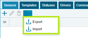
It is also possible to export the created sensors or import them using the Import/Export button.
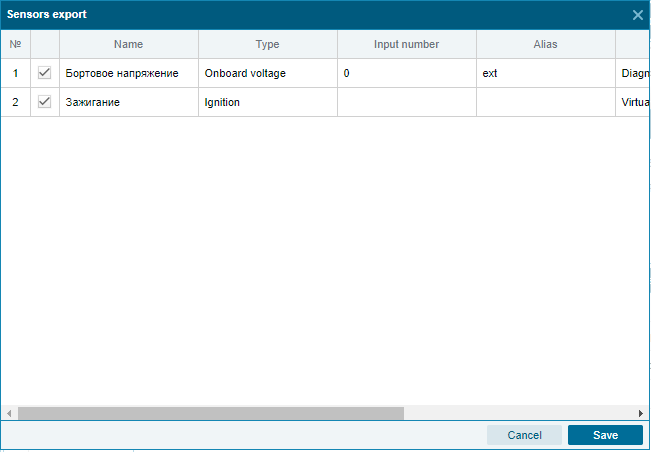
When exporting sensors, you can select a list of sensors and the need to upload their calibration tables and event templates to a *.csv file.
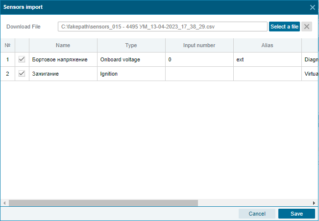
When importing, you can also make a similar selection.
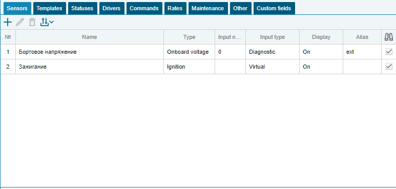
The created sensors are shown in a table with the following columns:
№ - serial number of the sensor;
name, type, input number and input type - fields of the same name specified in the sensor properties;
display - flag for displaying the sensor in the tooltip of the monitoring panel;
alias - variable to be set using the current sensor in the formulas of virtual sensors;
 sensor activity - activates/deactivates the sensor. In the off state, the sensor does not participate in event detection and other calculations for the object.
Button  "Add" is designed to add a new sensor to the object.
The following fields are available in the add sensor dialog:
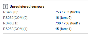
Type – selection of sensor connection type (simple/virtual). The simple type is used when entering physical sensors that are displayed in the dashboard as unregistered sensors or in the navigation report as non-calibrated.
The virtual sensor connection type allows you to create a sensor that uses other sensors. When selected, the "Function" field opens.
Alias – set variable for special formulas of the virtual sensor, using the current sensor;
Sensor type - determines the type of sensor usage and is selected from the list of available, divided into groups. The sensor type must match the characteristics of the equipment installed on the site, otherwise the calculations may be incorrect.
Digital
Ignition - a sensor that indicates whether the ignition is on or off. Used in event templates "Engine operation", "Idling", "Stop", "Random sensor operation";
Panic button - a sensor that indicates the operation of the panic button (SOS). Used in the "Alarm" event template;
Indicators
Onboard voltage - used to force the selection of the onboard voltage source or convert its value. By default, the onboard voltage is taken from the diagnostic input number 0;
Engine speed - a sensor showing the engine speed;
Engine temperature - a sensor that displays the temperature of the engine;
Trailer temperature - a sensor showing the temperature of the trailer;
Relative engine hours - a sensor that allows you to calculate the engine hours of a vehicle relative to the coefficient, more details in the article Relative engine hours . If a sensor with this type is created, then Engine hours both in reports and in Norms are calculated taking into account this sensor;
Mileage sensor - this sensor allows you to replace the mileage calculated according to GPS data with the mileage transmitted from the on-board computer of the car. After creating the sensor, you must specify the Mileage calculation parameter in the Norms as Mileage sensor .
Fuel
Fuel consumption - gauge showing fuel consumption;
Fuel level - a sensor that determines the level of fuel in the tank. Used in event templates "Refueling" and "Draining";
Fuel distribution - a sensor that determines the amount of fuel dispensed by the tanker. It is used in the event template "Refueller operation" - based on its operation, the "Refueling list" report is generated;
Fuel level in the tank - a sensor that determines the level of fuel in the tank. Used in the event templates "Tank filling" and "Tank emptying";
Identification
RFID of the unit - a sensor with which you can fix the assignment of the unit (trailer) to the object;
Driver's RFID - a sensor that can be used to record the driver's assignment to an object;
Agro
Combine auger - a sensor showing the operation of the auger. Used in the "Auger unloading" event template;
Grain level - a sensor that determines the level of grain in the bunker. It is used in the event templates "Loading grain" and "Unloading grain" - based on its work, the report "Unloading combines" is generated;
Weight terminal - a sensor with which you can control and account for loads at weighing stations. Used in the event template "Weight terminal";
Road builders
Front blade - a sensor showing the operation of the front blade. Used in the "Blade operation" event template;
Body lift - a sensor that indicates body lifts. Used in the "Other" event template;
The gritter is a sensor that indicates the operation of the gritter. Used in the "Gritter Operation" event template;
Middle blade - a sensor showing the operation of the middle blade. Used in the "Grader bucket operation" event template;
Road brush - a sensor showing the operation of the road brush. Used in the "Brush operation" event template;
Road mower - a sensor showing the operation of a road mower. Used in the "Mower operation" event template;
Other
Crane operation - a sensor showing the operation of the crane. Used in the "Crane operation" event template;
Concrete unloading - a sensor that records the unloading of concrete from the mixer. Used in the "Mixer unloading" event template;
Concrete mixer operation - a sensor showing the operation of the concrete mixer. Used in the "Mixer transport" event template;
Power take-off - a sensor indicating the inclusion of the power take-off. Used in the event template "COM operation";
Garbage Rise - Gauge indicating debris rises. Used in the "Garbage Pickup" and "Garbage Pickup Count" event templates;
GNSS jamming sensor - allows you to determine the fact of GNSS signal jamming. Used in the "GNSS Jamming" event template;
Custom sensor - a sensor that can be configured to measure any indicator. Depending on the settings, it can be used in the event templates "Operation of an arbitrary sensor" and "Number of triggers of an arbitrary sensor".
Sensor name - the name of the sensor displayed in the list of sensors. Initially generated based on sensor type and number automatically and can be edited by the user.
Input type - select the type of interface through which the sensor is connected to the terminal (discrete, analog, pulse, RS232(COM), RS485, CAN bus, diagnostic, 1-Wire, frequency, BLE). The type of entry is determined from the information panel of the object card or according to the navigation report.
Input number - the sequence number of the input through which information enters the system. Numbering starts from 0.
Function - the field becomes available when you select the type of sensor connection "Virtual" and allows you to select the aggregating function "sum", "average" or "expression".
The aggregating functions "sum" and "average" allow you to add physical sensors to the virtual sensor, which will be calculated as the sum of the sensors or their average value.
The aggregating function "expression" allows you to use a special formula in the field of the same name.
Formula - the field becomes available when you select the sensor connection type "Virtual" and the aggregating function "expression". The reference book of functions and parameters of the virtual sensor with examples is available by clicking the button or by link
Calibration type – enables/disables sensor calibration. The list of available calibration types depends on the input type and sensor type.
By default - tare is not used;
On/Off - discrete sensor, below in the Form you can specify the text that will be displayed instead of On. or Off. ;
Table - the output value is calculated in accordance with the calibration table, while the input parameters less than the first and greater than or equal to the last line are considered invalid and ignored. Thus, it is possible to cut off bursts / drops in the fuel level more / less than the maximum allowable;
Accumulator - converts the input parameters into an accumulated value. For sensors of this type, the calculation table is applied to the difference between two adjacent messages. Used for flow meters and signal pickup devices. Also, for this type of calibration, you can specify the maximum value of the parameter in the Max. value . In the case when the parameter value reaches the maximum and jumps, the system will correctly calculate the "zeroing" of the sensor;
The difference from before - also converts the input parameters to an accumulated value. Unlike the accumulator, it counts the input parameters since the previous measurement (message). For sensors of this type, the calculation table is applied to the difference between two adjacent messages. It is used for instantaneous flow sensors when the device transmits not the accumulated value of pulses, but the number of pulses between messages.
Invert - enables/disables the inversion of the discrete state of the sensor.
Display in tooltip - enables/disables the display of the sensor in the object's tooltip (a tooltip that the user opens by clicking on the element) of the monitoring window.
Enable median filtering - allows you to apply a smoothing algorithm to the sensor readings. In the field, you must specify the degree of such smoothing from 0 to 255. The degree of filtering can be applied to the following types of sensors: on-board voltage, engine speed, engine temperature, trailer temperature, fuel, fuel level, fuel level in the tank, arbitrary.
Display last valid value - enables/disables fixing the last valid value received from the sensor.
Color on chart - allows you to select the color for displaying the sensor on charts.
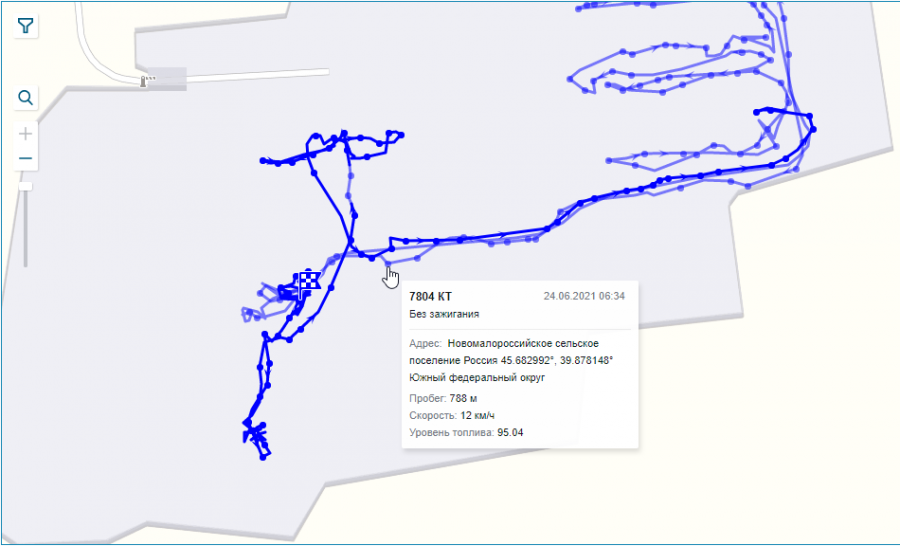
Display track without ignition on - the option is available for the "ignition" sensor type and affects the visibility of object movements without the ignition on on the map when generating the "Track" report. The feature works for both web and mobile versions.
In the monitoring system, the presence of ignition is an additional confirmation of the movement of the object. If it is necessary to display all movements of an object on the map when generating the "Track" report, then it is necessary to enable the corresponding option in the sensor settings. When this option is enabled, in addition to the main track, the map will also display the track of the object without the ignition on. The track will be painted in a translucent color, and tooltips when you hover over a track point will contain a note that the object moved without ignition on this section.
Display on the graph as a fuel level sensor "- the option is available for the "fuel consumption" sensor type and affects the display of the fuel consumption sensor on the graph of the "Track" report. When the option is enabled, the fuel consumption graph is displayed as a level and allows you to visually compare the readings of the fuel consumption and fuel level sensors. The line of the graph goes down with the increase in consumption, while it rises when the "Refill" event is detected. When the option is enabled, the graph of fuel consumption readings starts from the graph readings of a simple or virtual fuel level sensor. If the object has several fuel level sensors installed, but there is no virtual one, the fuel consumption graph starts from the fuel level graph that has a higher value at the beginning of the period requested in the report. If the object does not have a fuel level sensor, then when the option is enabled, the graph of the fuel consumption sensor is inverted.
Calibration table - the tab is available when selecting the types of calibration table, accumulator and difference from previous. and is designed to convert data that comes from a specific input into sensor values. For example, an abstract input value of 42 can be converted to 15 liters of fuel at the output.
The tab "Calibration table" is divided into two parts: on the left, the input value that comes from the equipment and the output value that should be used in reports are indicated. The graph of the calculation result is displayed on the right.
At the top of the tab there is a taring control panel, through which you can add a new line, or
  delete the existing one and also import
 table via the clipboard, after copying it from another sensor by clicking the button
 or from an Excel spreadsheet.
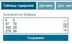
The Save button replaces table rows with clipboard values.
Button allows you to go to the historical list of calibration tables. More details about the functionality can be found in the article .
Sensors - the tab becomes available when you select the virtual type of sensor connection with the aggregating function "sum" or "average".
At the top of the “sensors” tab there is a control panel for aggregated sensors, through which you can add or
  remove sensors.
Active sensors added in this way are excluded from displaying in the charts and the object tooltip separately. The virtual sensor will be displayed.
Add. settings - the tab becomes available when you select the type of sensor "Arbitrary" and allows you to fine-tune the sensor depending on the scope of its application.
Type - allows you to select sensor presets from the "Discrete" and "Analog/Pulse" profiles.
A discrete profile activates the capture of an operation event and the display of the sensor in the payload graph with the rendering type Area.
The analog/pulse profile activates the display of the sensor in the payload graph with the Line drawing type.
Capture work events - adds the "Operation Sensor_name" event template, the name of which can be changed in the "Operation event name" field.
Fix the number of triggers - the option becomes available when the "Fix operation event" checkbox is enabled and adds the event template "Number of triggers Sensor_name", the name of which can be changed in the "Name of triggers events" field.
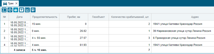
Sensor triggering by selected conditions can be tracked in a separate tab of the "Track" report.
Display on the map - the option becomes available when the "Fix the number of triggers" checkbox is enabled and displays the sensor triggering on the map.
The sensor operation icon displayed in the “Track” report can be selected from the library.
The options Show on the object chart and Show on the payload chart allow you to enable the display of sensor operation readings in the object and payload charts as a line or area by selecting the appropriate drawing type. The "Area" drawing type is used for discrete sensors, and "Line" for all others.