Analog FLS setting
A feature of analog sensors is that when the ignition is turned off and on, according to the parameter from which the readings are taken, messages with false data are received for several seconds until the desired value is reached. It is necessary to cut off the period with false data.
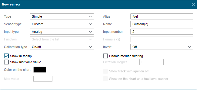
If data from an analog sensor is received by the parameter in * or adc *, where * is the input number, then you can use them directly. Otherwise, you must first create a sensor with the type Simple , sensor type Arbitrary , input type Analog . Specify the number of the input through which the data is received. We also specify an alias, in our case fuel .
When creating a fuel level sensor, we need to set its type to Virtual , sensor type to Fuel Level , and function to Expression , which will allow us to enter a Formula. Specify the type of calibration as Table .
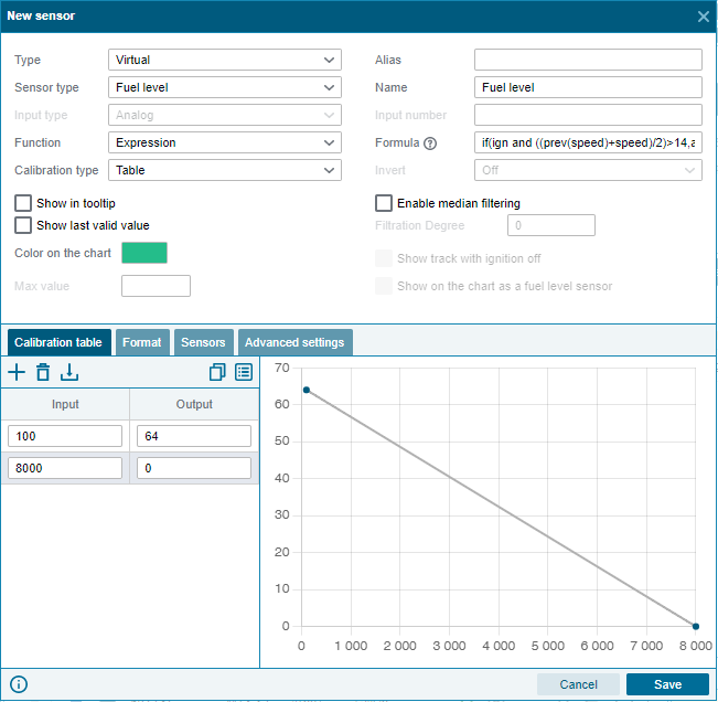
The formula creates a function that checks for the presence of two conditions: the ignition is on and the speed is higher than the specified one. The function will cut off the period when false values were received in the analog sensor. Feature Reference .
if(ign and ((prev(speed)+speed)/2)>14,adc2,0)
here ign is the alias of the ignition sensor, ((prev(speed)+speed)/2)>14 - checking the condition that the average speed of the object between two messages is greater than 14 km/h. The average speed between messages is calculated to reduce the effect of speed fluctuations due to shielding while stationary. adc2 is the parameter from which the values of the fuel level sensor are read, earlier we created an arbitrary sensor with the alias fuel , which can be used in this formula instead of adc2 . In this formula, you can change the speed, the higher, the more the vehicle needs to accelerate so that the data is not discarded.
We also enable Median filtering , which will allow us to smooth the graph and get fewer fuel surges. You can, as in the example, start with a value of 20, and change depending on how often false fuel surges occur.
After configuring the fuel level sensor , it is necessary to configure the Filling and Draining templates . They are located in the Templates tab .
In the Filling and Draining templates , the settings are the same. It is necessary to change the condition Parameter value , circled in blue, reduced to 1 s. Thus, the sensor will be more sensitive to vibrations. If any gas stations are not displayed, set the value to 0 sec or remove this condition.
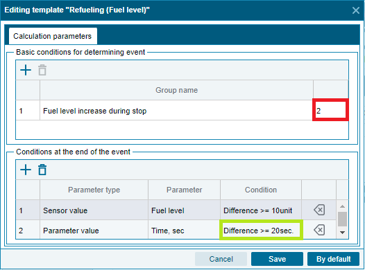
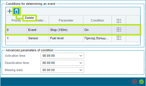
We double-click on the parameter circled in red and the Conditions for defining an event window opens . Here we delete the event Stop (150m) . This change will allow tracking fillings and drains when the Stop (150m) event is inactive .