Examples of sensors
Simple sensors
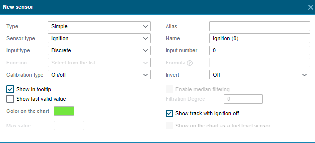
Ignition by discrete input
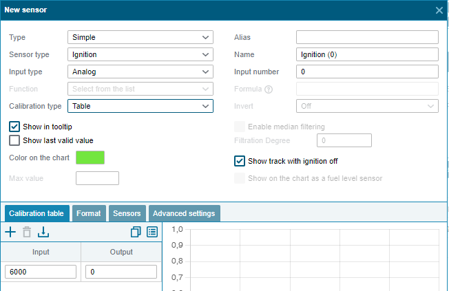
Ignition by analog input (the sensor will trigger if the voltage is more than > 6000 mV)
Fuel dispensing from counting pulse input
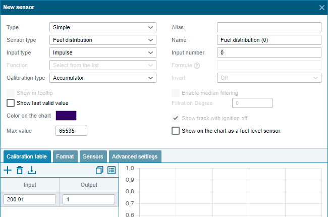
Depending on the pulse counting algorithm, the terminal selects the type of calibration "Accumulator" or "Difference from the previous".
Similarly, sensors for flow-through fuel flow meters are created - in this case, the type of sensor should be selected as "Fuel consumption".
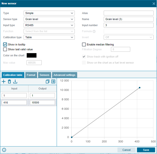
Grain level received via RS485 interface
Fuel level received via RS485 interface
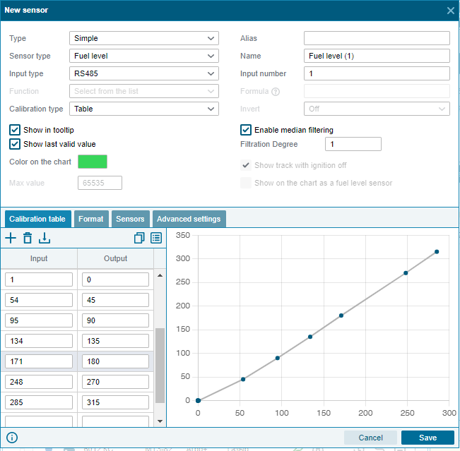
Because values less than the first and greater than or equal to the last row are considered invalid and are ignored, it is recommended to add an input value higher than the maximum possible in the last row of the table. For example, 1024 or 4096 for sensors that transmit the maximum fuel level in the ranges of 0-1023 or 0-4095. The output value can be calculated linearly.
Trailer temperature received via 1-Wire interface

Virtual
On-board voltage ignition sensor
GNSS signal suppression received from the UMKa3xx terminal
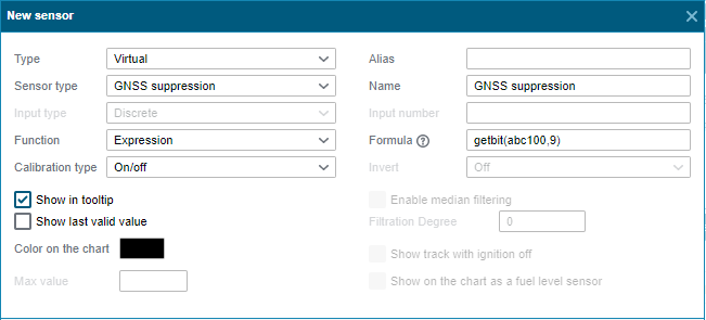
For UMK-3xx terminals, the STATUS field is displayed in decimal form at the input *А(100), GNSS signal suppression changes the ninth bit. In the sensor, set the expression getbit(adc100,9)
Fuel level with an aggregation function for summing or averaging.
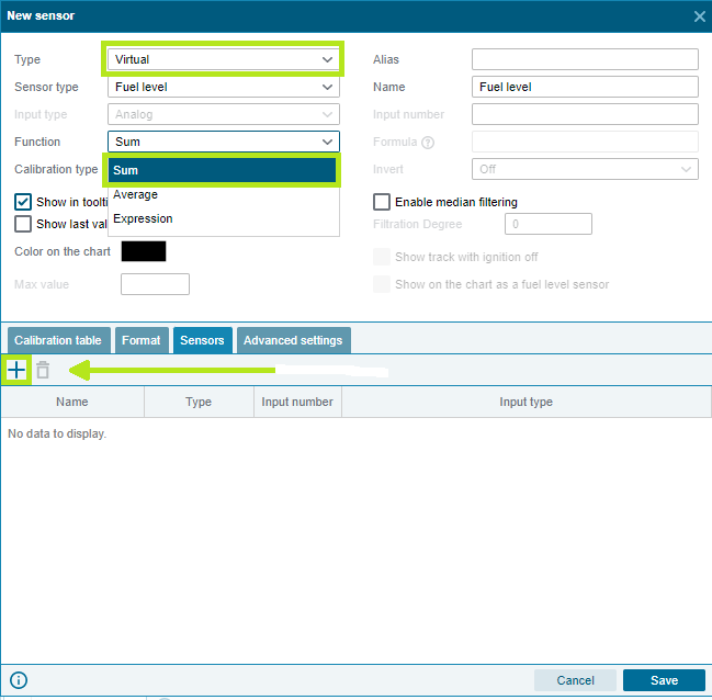
The aggregating function "Sum" is used when one fuel level sensor is installed in each tank .
The aggregating function "Average" is used when several fuel level sensors are installed in one tank .
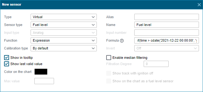
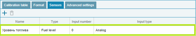
Fuel level with ignition validation
When using standard fuel sensors with an inverted calibration table, an effect occurs when the voltage from the sensor drops to 0 when the ignition is turned off, which is detected as a full tank. For filtering, you can use validation by the ignition sensor.
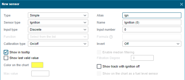
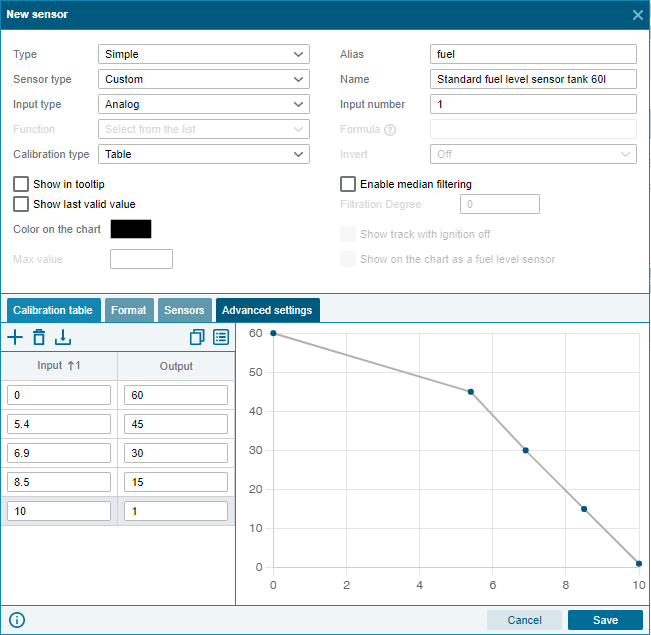
To do this, we create physical sensors for ignition and fuel level, indicating the aliases ign and fuel
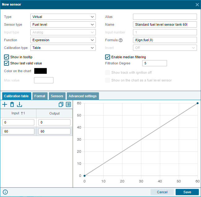
Then we create a virtual fuel level sensor with the expression if(ign, fuel, 0) - if the ignition is on, then we transfer the fuel as it is, otherwise we transfer 0 instead. Fill in the calibration table with 2 lines - 0 - 0 and maximum_tank_volume - maximum_tank_volume, which will cut off the 0 obtained from the formula condition. As a result, the system will consider invalid the fuel level obtained with the ignition sensor turned off.
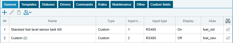
Fuel level on the sensor with the changed input number.
To do this, we create physical sensors with the Arbitrary type, calibration tables, old and new input numbers, and specifying fuel_old and fuel_new aliases.
Then we create a virtual fuel level sensor with the expression if(time > cdate('2021-12-22 00:00:00', 'yyyy-MM-dd HH:mm:ss'), fuel_new, fuel_old) - after 2021-12 -22 00:00:00 (UTC time) fuel is displayed from the new FLS, and up to this time inclusive from the old FLS.